How to make Table Grinding Machine?
Summary
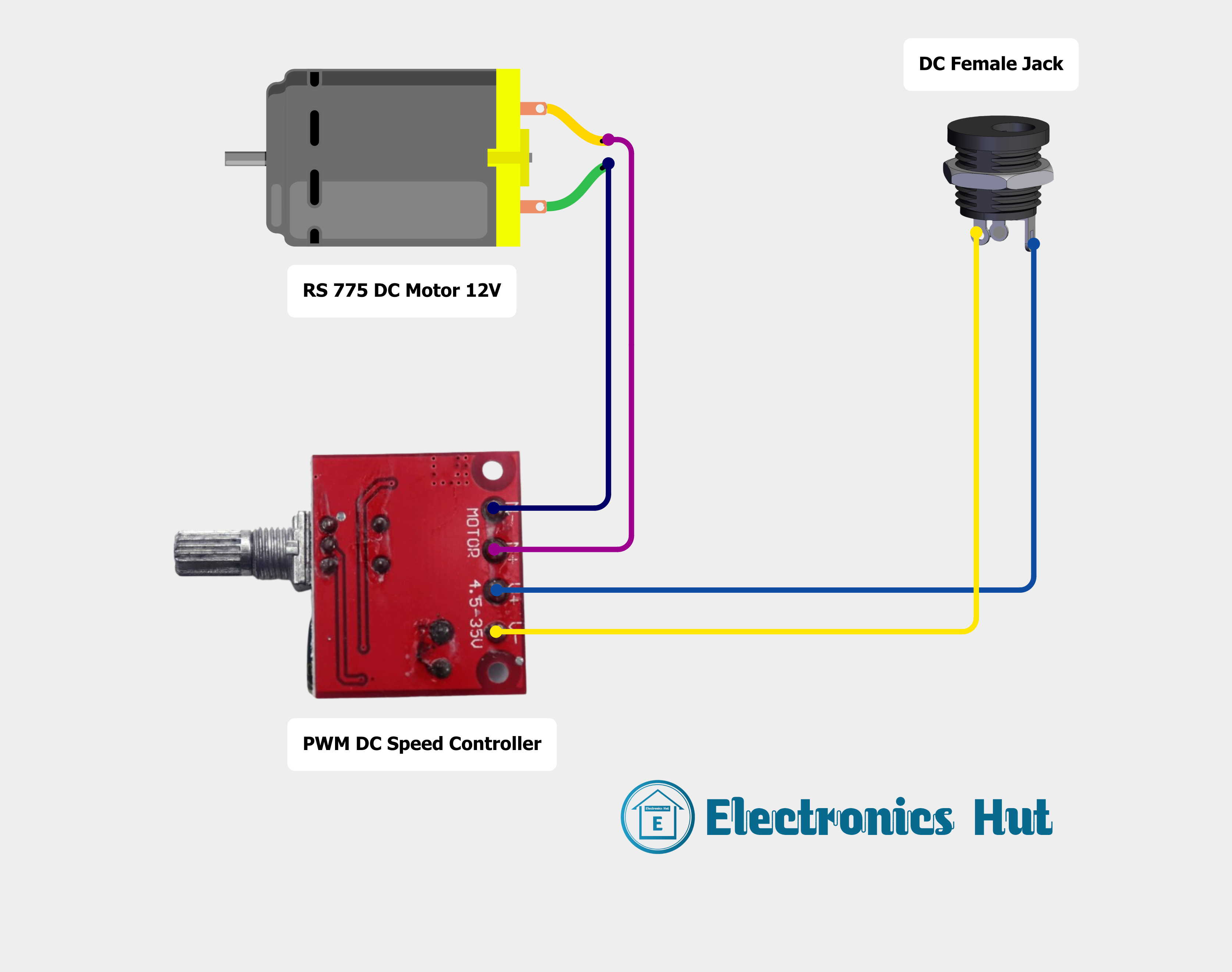
The circuit in is designed of a DC motor using a PWM (Pulse Modulation) DC Controller. The circuit is powered through a DC female jack, connects to an source. The PWM modulates power delivered to the motor, allowing for adjustable speed control. The is straightforward, consisting the motor, controller, and the input jack.
Component List
PWM Controller
- Description: A device that controls speed of a DC motor by pulse of the power signal.
- Pins: Motor Negative, Motor Positive, Voltage Positive, Voltage Negative
- Purpose: To regulate of the connected DC motor by varying the voltage and current.
DC Motor
- Description: An electric that runs on direct current (DC) electricity.
- Pins: pin 1, 2
- Purpose: perform mechanical work powered the PWM controller.
DC Female Jack
- Description: A connector provides interface for a DC power supply connect to the circuit.
- Pins: negative, detect, positive
- Purpose: To supply power to the PWM controller, in turn drives DC motor.
Comments
- Description: Placeholder that may represent annotations or notes in the design.
- Pins: N/A
- Purpose: provide additional information or clarification within the circuit design. These not a direct function in the electrical of the circuit.
Wiring Details
PWM Motor Controller
- Motor Negative is to DC Motor pin 1.
- Motor Positive is connected DC Motor pin 2.
- Voltage Positive connected DC female jack positive.
- Negative is connected to DC female jack negative.
DC Motor
- pin 1 is connected to PWM DC Speed Motor Negative.
- pin 2 to PWM Speed Motor Positive.
DC Female Jack
- positive is connected PWM Motor Speed Controller Voltage Positive.
- negative is connected to DC Motor Speed Controller Voltage Negative.
- detect in this circuit.
Documentation
This documentation provides an overview of circuit's components, their purpose, how they are together. The circuit controlling a DC motor's speed via a PWM controller, power supplied a DC jack. No programming is in the operation of this or programmable devices are included in the design.
Making Process
1. We have to take wood pieces with dimentions 46X35 cm 1 Nos, 40X3o cm 1 Nos, 30X15 cm 2 Nos, 36X15 cm 2 Nos.2. Using these pieces of wood we can make a box.
3. We need to make a step in the box to fit the motor (you can understand by watching the video above).
4. We can mount the motor to the box using a clamp (I made the clamp by heating the PVC pipe.).
5. Complete the connections as shown in the circuit diagram below..
6. After successful connections we can install 5inch grinding wheel or metal cutting blade..
7.By increasing the speed we can cut PVC pipes grind PVC or metal with the help of DC motor speed controller..
Please watch the full video above to understand the making process.
Circuit Diagram
How to make Mini Drill Machine using PVC?
Summary
The circuit described by the provided inputs consists of a DC female jack, a DC motor, a toggle switch, and a 2-pin push switch. The circuit is designed to control the operation of the DC motor using the toggle switch and the push switch. The DC female jack serves as the power input for the circuit. There are no microcontrollers or embedded code associated with this circuit as per the provided inputs.
Component List
DC Female Jack
- Description: A connector for supplying power to the circuit.
-
Pins:
- Negative
- Plug Detect
- Positive
DC Motor
- Description: An electromechanical device that converts electrical energy into mechanical motion.
-
Pins:
- Pin 1
- Pin 2
Toggle Switch
- Description: A switch that can connect or disconnect the circuit in one of two positions.
-
Pins:
- Output 1 +
- Input +
- Output 2 +
2Pin Push Switch
- Description: A momentary switch that closes the circuit when pressed.
-
Pins:
- Input +
- Output +
Wiring Details
DC Female Jack
- Positive: Connected to the Input + of the 2Pin Push Switch and the Input + of the Toggle Switch.
- Negative: Connected to Pin 1 of the DC Motor.
- Plug Detect: Not connected in this circuit.
DC Motor
- Pin 1: Connected to the Negative of the DC Female Jack.
- Pin 2: Connected to the Output + of the 2Pin Push Switch and the Output 1 + of the Toggle Switch.
Toggle Switch
- Input +: Connected to the Positive of the DC Female Jack.
- Output 1 +: Connected to Pin 2 of the DC Motor.
- Output 2 +: Not connected in this circuit.
2Pin Push Switch
- Input +: Connected to the Positive of the DC Female Jack.
- Output +: Connected to Pin 2 of the DC Motor.
Making Process
1. We have to take a PVC pipe with a width of 11cm and a diameter of 4cm.
2. I am taking 2 PVC sheets to cover the two holes of the PVC pipe.
3. Here we are taking RS-555 12V DC motor and we have taken PVC pipe fits this motor.
4. We need to drill holes to fit the motor into a sheet and holes to fit the DC female jack and 3pin toggle switch.
5. We need to fasten the sheets to the motor with screws.
6. Complete the connections as shown in the circuit diagram below.
7. We need to tie the other side of the pipe with sheet, cut the excess part of the sheet and grind the uneven part.
8. Clamp the drill chuck to the motor shaft.
Please watch the full video above to understand the making process.
Circuit Diagram

How to make Soldering Helping Hand using Geometry Compass?
Componets List
- Wood piece
- Bolts and Nuts
- Compass 2 Nos
- Alligator Crocodile Clips
- Spring
Making Process
1. We need to take a piece of wood less than 8X4 inches in size.
2. Drill holes in the piece of wood to fit the compass and spring.
3. Fasten the compass and solder holder spring to the wood using bolts and nuts.
4. Attach alligator crocodile clips to each compass using fast glue..
Please watch the full video above to understand the making process.
How to make Variable Bench Power Supply using PVC?
Summary
This circuit is designed to step down and regulate voltage from a Switched-Mode Power Supply (SMPS) to various components including a mini digital volt/ammeter, a USB A DC to DC buck converter charging step-down module, a fan, and other peripherals. The circuit utilizes two buck converters (LM2596S and XL4016) to adjust the voltage levels for different parts of the circuit. A mini digital volt/ammeter is used to monitor the voltage and current, while a fan is powered by the LM2596S buck converter. The circuit is interfaced with Banana Female Plugss and a DC female jack for external connections. A round rocker switch is used to control the power from the SMPS. The circuit is designed for applications requiring regulated DC power with monitoring capabilities.
Component List
LM2596S 5A DC Buck Step-down
- Description: A DC-DC step-down (buck) converter capable of driving a 5A load with high efficiency.
- Pins: Output +, Output -, Input +, Input -
XL4016
- Description: A DC-DC step-down (buck) converter.
- Pins: Input +, Input -, Output -, Output +
Banana Female Plugs
- Description: A single-wire electrical connector used for joining wires to equipment.
- Pins: Negative, Positive
Mini Digital Volt/Ammeter
- Description: A compact digital meter for measuring voltage and current.
- Pins: Gnd, Vin, Vread, Vsupply
SMPS
- Description: A switched-mode power supply providing multiple output voltages.
- Pins: Line, Neutral, Ground, Common 1, Common 2, Common 3, Voltage 1 +, Voltage 2 +, Voltage 3 +
DC female jack
- Description: A female DC power connector typically used for connecting a power supply to a device.
- Pins: negative, plug detect, positive
USB A DC to DC Buck Converter Charging Step Down Module
- Description: A USB-powered buck converter module for charging and power supply applications.
- Pins: Input -, Input +
Fan
- Description: A small DC fan for cooling purposes.
- Pins: GND, 12V
3Pin Panel Mount
- Description: A panel mount connector with three pins for power connections.
- Pins: Ground, Negative, Positive
Round Rocker Switch
- Description: A simple on-off switch for controlling power flow.
- Pins: Input +, Ground, Output +
Wiring Details
LM2596S 5A DC Buck Step-down
- Output +: +: Connected to the 5V pin of the Fan and Vsupply of the Mini Digital Volt/Ammeter.
- Output -: Connected to the GND pin of the Fan and Gnd of the Mini Digital Volt/Ammeter.
- Input +: Connected to Voltage 2 + of the SMPS.
- Input -: Connected to Common 2 of the SMPS.
XL4016
- Output -: Connected to the Vin pin of the Mini Digital Volt/Ammeter.
- Output +: Connected to the Vread pin of the Mini Digital Volt/Ammeter, Input + of the USB A DC to DC Buck Converter, and Positive of the Banana Plug.
- Input -: Connected to Common 1 of the SMPS.
- Input +: Connected to Voltage 1 + of the SMPS..
Banana Female Plugs
- Negative:Connected to Input - of the USB A DC to DC Buck Converter, Gnd of the Mini Digital Volt/Ammeter, and negative of the DC female jack.
- Positive: Connected to Output + of the XL4016.
Mini Digital Volt/Ammeter
- Gnd: Connected to Output - of the LM2596S, Input - of the USB A DC to DC Buck Converter, and Negative of the Banana Plug.
- Vin: Connected to Output - of the XL4016.
- Vread: Connected to Output + of the XL4016.
- Vsupply: Connected to Output + of the LM2596S.
SMPS
- Line: Connected to Output + of the Round Rocker Switch.
- Neutral: Connected to Negative of the 3Pin Panel Mount.
- Ground: Connected to Ground of the 3Pin Panel Mount.
- Common 1: Connected to Input - of the XL4016.
- Common 2: Connected to Input - of the LM2596S.
- Voltage 1 +: Connected to Input + of the XL4016
- Voltage 2 +: Connected to Input + of the LM2596S.
DC female jack
- negative: Connected to Input - of the USB A DC to DC Buck Converter and Negative of the Banana Plug.
- positive: Connected to Output + of the XL4016.
USB A DC to DC Buck Converter Charging Step Down Module
- Input -: Connected to Gnd of the Mini Digital Volt/Ammeter, Negative of the Banana Plug, and negative of the DC female jack.
- Input +: Connected to Output + of the XL4016.
Fan
- GND: Connected to Output - of the LM2596S.
- 12V: Connected to Output + of the LM2596S.
3Pin Panel Mount
- Ground: Connected to Ground of the SMPS.
- Negative: Connected to Neutral of the SMPS.
- Positive: Connected to Input + of the Round Rocker Switch.
Round Rocker Switch
- Input +: Connected to Positive of the 3Pin Panel Mount.
- Ground: Not connected in the provided net list.
- Output +: Connected to Line of the SMPS.
Making Process
Please watch the full video above to understand the making process.
Circuit Diagram

How to make Non-Rechargeable Kids laptop to Rechargeable?
Summary
The circuit in question appears to be a charging system designed to charge 18650 Li-ion batteries using a TP4056 charging module. The system also includes a laptop as a load or possibly as a power source for the charging module. The circuit does not include any microcontroller or embedded code.
Component List
TP4056 Charging Module
- Description: A module used for charging lithium-ion batteries, typically through a type port.
- Purpose: To manage the charging of the 18650 Li-ion batteries, ensuring they are charged safely and efficiently.
18650 Li-ion Battery (Battery 1)
- Description: A standard rechargeable lithium-ion cell commonly used in high-drain applications.
- Purpose: To store electrical energy that can be used to power devices or, in this case, to be charged by the TP4056 module.
18650 Li-ion Battery (Battery 2)
- Description: Identical to the first battery, this is another standard rechargeable lithium-ion cell.
- Purpose: Similar to the first battery, it stores electrical energy and may be used in parallel with the first battery to increase capacity or in another configuration.
Laptop
- Description: A portable computer that can be powered by an internal battery or external power source.
- Purpose: In this circuit, the laptop's role is not entirely clear. It could be the power source for the TP4056 charging module or a load that is powered by the charged batteries.
Wiring Details
TP4056 Charging Module
-
Connections:
- Connected to the positive pin of Battery 2.
- Connected to the negative pin of Battery 1.
- Connected to the "Power +" and "Power -" pins of the Laptop.
18650 Li-ion Battery (Battery 1)
-
Connections:
- The negative pin is connected to the TP4056 Charging Module.
18650 Li-ion Battery (Battery 2)
-
Connections:
- The positive pin is connected to the TP4056 Charging Module.
- The negative pin is connected to the positive pin of Battery 1, indicating a series connection between the two batteries.
Laptop
-
Connections:
- The "Power +" pin is connected to the TP4056 Charging Module.
- The "Power -" pin is connected to the TP4056 Charging Module.
Making Process
Please watch the full video above to understand the making process.
Circuit Diagram

How to burn bootload and programming to Microcontroller?
Summary
This circuit is designed around the Arduino UNO platform, incorporating an ATMEGA328 microcontroller as the primary processing unit. The circuit includes a crystal oscillator with associated capacitors for clock generation, a resistor for potential pull-up or pull-down configuration, and power supply connections. The Arduino UNO board serves as the development environment for the ATMEGA328, providing power and a set of digital and analog I/O pins. The circuit's functionality is determined by the embedded code uploaded to the Arduino UNO, which is based on the ATMEGA328 microcontroller.
Component List
Arduino UNO
- Description: A microcontroller board based on the ATMEGA328P.
- Pins: UNUSED, IOREF, Reset, 3.3V, 5V, GND, Vin, A0-A5, SCL, SDA, AREF, D0-D13.
ATMEGA328
- Description: A low-power CMOS 8-bit microcontroller based on the AVR enhanced RISC architecture.
- Pins: RESET, D0-D13, VCC, GND, CRYSTAL, AREF, A0-A5.
Crystal
- Description: A crystal oscillator used to provide a stable clock signal to the microcontroller.
- Pins: pin 0, pin 1.
Tantalum Capacitors (2x)
- Description: Capacitors used for decoupling and stabilizing the voltage supply.
- Capacitance: 22 pF (2.2e-11 Farads).
- Pins: -, +.
Resistor
- Description: A resistor that may be used for pull-up or pull-down purposes.
- Resistance: 10 kOhms.
- Pins: pin1, pin2.
Wiring Details
Arduino UNO
- D10 connected to ATMEGA328 RESET (via Resistor pin2).
- GND connected to ATMEGA328 GND, Tantalum Capacitor - (both capacitors).
- 5V connected to ATMEGA328 VCC (via Resistor pin1).
- D13 connected to ATMEGA328 D13.
- D12 connected to ATMEGA328 D12.
- D11 connected to ATMEGA328 D11.
ATMEGA328
- RESET connected to Arduino UNO D10 (via Resistor pin2).
- CRYSTAL connected to Crystal pin 0 (via Tantalum Capacitor +) and Crystal pin 1 (via Tantalum Capacitor +).
- GND connected to Arduino UNO GND, Tantalum Capacitor - (both capacitors).
- VCC connected to Arduino UNO 5V (via Resistor pin1).
- D13 connected to Arduino UNO D13.
- D12 connected to Arduino UNO D12.
- D11 connected to Arduino UNO D11.
Crystal
- pin 0 connected to ATMEGA328 CRYSTAL (via Tantalum Capacitor +).
- pin 1 connected to ATMEGA328 CRYSTAL (via Tantalum Capacitor +).
Tantalum Capacitors
- Capacitor 1 (+) connected to ATMEGA328 CRYSTAL and Crystal pin 0.
- Capacitor 1 (-) connected to ATMEGA328 GND.
- Capacitor 2 (+) connected to ATMEGA328 CRYSTAL and Crystal pin 1.
- Capacitor 2 (-) connected to ATMEGA328 GND.
Resistor
- pin1 connected to ATMEGA328 VCC and Arduino UNO 5V.
- pin2 connected to ATMEGA328 RESET and Arduino UNO D10.
Making Process
Please watch the full video above to understand the making process.
Circuit Diagram

How to make Smart Dust Bin?
Summary
This circuit is designed to control a servo motor based on the distance measurements from an HC-SR04 Ultrasonic Sensor. The system is powered by two 18650 Li-ion batteries connected in series, managed by a TP4056 Type-C Charging Module, and regulated by an LM2956 Buck Converter DC-DC to provide a stable voltage supply. The control logic is implemented on an ATMEGA328 microcontroller, which processes the sensor data and drives the servo motor accordingly. The circuit also includes a rocker switch for power control, capacitors for noise reduction and stability, and a resistor to set the microcontroller's RESET pin behaviour.
Component List
Servo Motor
- Description: A motor capable of precise angular positioning.
- Purpose: To actuate based on the distance measured by the ultrasonic sensor.
18650 Li-ion Battery
- Description: A rechargeable battery providing power to the circuit.
- Purpose: To supply electrical power to the circuit components.
HC-SR04 Ultrasonic Sensor
- Description: A sensor that measures distance by emitting ultrasonic waves.
- Purpose: To detect the distance to an object and provide this information to the microcontroller.
TP4056 Type-C Charging Module
- Description: A charging module for Li-ion batteries with a USB Type-C input.
- Purpose: To safely charge the 18650 Li-ion batteries and provide power output to the circuit.
LM2956 Buck Converter DC-DC
- Description: A DC-DC converter that steps down voltage to a lower level.
- Purpose: To regulate the battery voltage down to a level suitable for the microcontroller and other components.
Rocker Switch
- Description: A switch to control the power flow in the circuit.
- Purpose: To allow the user to turn the circuit on and off.
Ceramic Capacitor
- Description: A passive component used to store energy in an electric field.
- Purpose: To filter out voltage spikes and smooth the power supply.
ATMEGA328 Microcontroller
- Description: A popular 8-bit microcontroller with a variety of digital and analog I/O pins.
- Purpose: To process sensor data and control the servo motor.
Crystal
- Description: A timing device that provides a stable clock signal to the microcontroller.
- Purpose: To ensure accurate timing for the microcontroller's operations.
Resistor
- Description: A passive component used to limit current or divide voltages.
- Purpose: To pull up the RESET pin of the microcontroller to prevent unintentional resets.
Wiring Details
Servo Motor
- VCC: Connected to the positive output of the LM2956 Buck Converter.
- GND: Connected to the ground net, which includes the negative output of the LM2956 Buck Converter.
- Pulse: Connected to digital pin D7 of the ATMEGA328 microcontroller.
HC-SR04 Ultrasonic Sensor
- VCC: Connected to the positive output of the LM2956 Buck Converter.
- GND: Connected to the ground net.
- TRIG: Connected to digital pin D9 of the ATMEGA328 microcontroller.
- ECHO: Connected to digital pin D8 of the ATMEGA328 microcontroller.
TP4056 Type-C Charging Module
- B+: Connected to the positive terminal of the 18650 Li-ion Battery.
- B-: Connected to the negative terminal of the 18650 Li-ion Battery.
- OUT+: Connected to the input of the rocker switch.
- OUT-: Connected to the negative output of the LM2956 Buck Converter.
LM2956 Buck Converter DC-DC
- IN+: Connected to the output of the rocker switch.
- IN-: Connected to the OUT- of the TP4056 Type-C Charging Module.
- OUT+: Connected to the VCC net, supplying power to the microcontroller, sensor, and servo.
- OUT-: Connected to the ground net.
Rocker Switch
- Input:Connected to the OUT+ of the TP4056 Type-C Charging Module.
- Output: Connected to the IN+ of the LM2956 Buck Converter.
Ceramic Capacitors
- Pin0: Connected to the ground net.
- Pin1: Connected to the CRYSTAL pins of the ATMEGA328 microcontroller.
ATMEGA328 Microcontroller
- VCC: Connected to the positive output of the LM2956 Buck Converter.
- GND: Connected to the ground net.
- D7, D8, D9: Connected to the servo and ultrasonic sensor as described above.
- CRYSTAL: Connected to the crystal and ceramic capacitors for clock stability.
- RESET: Connected to the resistor to ensure proper reset behavior.
Crystal
- Pin 0, Pin 1: Connected to the CRYSTAL pins of the ATMEGA328 microcontroller and ceramic capacitors.
Resistor
- Pin1: Connected to the RESET pin of the ATMEGA328 microcontroller.
Pin2: Connected to the VCC net.
Documented Code
Source Code
                    // Define Pins

                    #include <Servo.h>


                    Servo servo;


                    int trigPin = 9;

                    int echoPin = 8;


                    // Defines variables

                    long duration;

                    int distance;


                    void setup()

                    {

                    servo.attach(7);

                    servo.write(0);

                    delay(2000);


                    // Sets the trigPin as an Output

                    pinMode(trigPin, OUTPUT);

                    // Sets the echoPin as an Input

                    pinMode(echoPin, INPUT);

                    // Starts the serial communication

                    Serial.begin(9600);

                    }


                    void loop()

                    {

                    // Clears the trigPin

                    digitalWrite(trigPin, LOW);

                    delayMicroseconds(2);

                    // Sets the trigPin on HIGH state for 10 micro seconds

                    digitalWrite(trigPin, HIGH);

                    delayMicroseconds(10);

                    digitalWrite(trigPin, LOW);

                    // Reads the echoPin, returns the sound wave travel time in microseconds

                    duration = pulseIn(echoPin, HIGH);

                    // Calculating the distance

                    distance= duration*0.034/2;

                    // Prints the distance on the Serial Monitor

                    Serial.print("Distance: ");

                    Serial.println(distance);

                    if (distance <= 25) // Change Distance according to Ultrasonic Sensor Placement

                    {

                    servo.write(0);

                    delay(3000);

                    }

                    else

                    {

                    servo.write(110);

                    }

                    }
This code is for the ATMEGA328 microcontroller. It initializes a servo motor and an HC-SR04 Ultrasonic Sensor. The sensor measures the distance to an object, and if the distance is less than or equal to 25 units (adjustable based on sensor placement), the servo is set to one position; otherwise, it is set to another position. The code includes setup routines for the servo and sensor pins and a loop that continuously measures distance and controls the servo.
Making Process
Please watch the full video above to understand the making process.
Circuit Diagram

How to make RFID Based Attendance System?
Summary
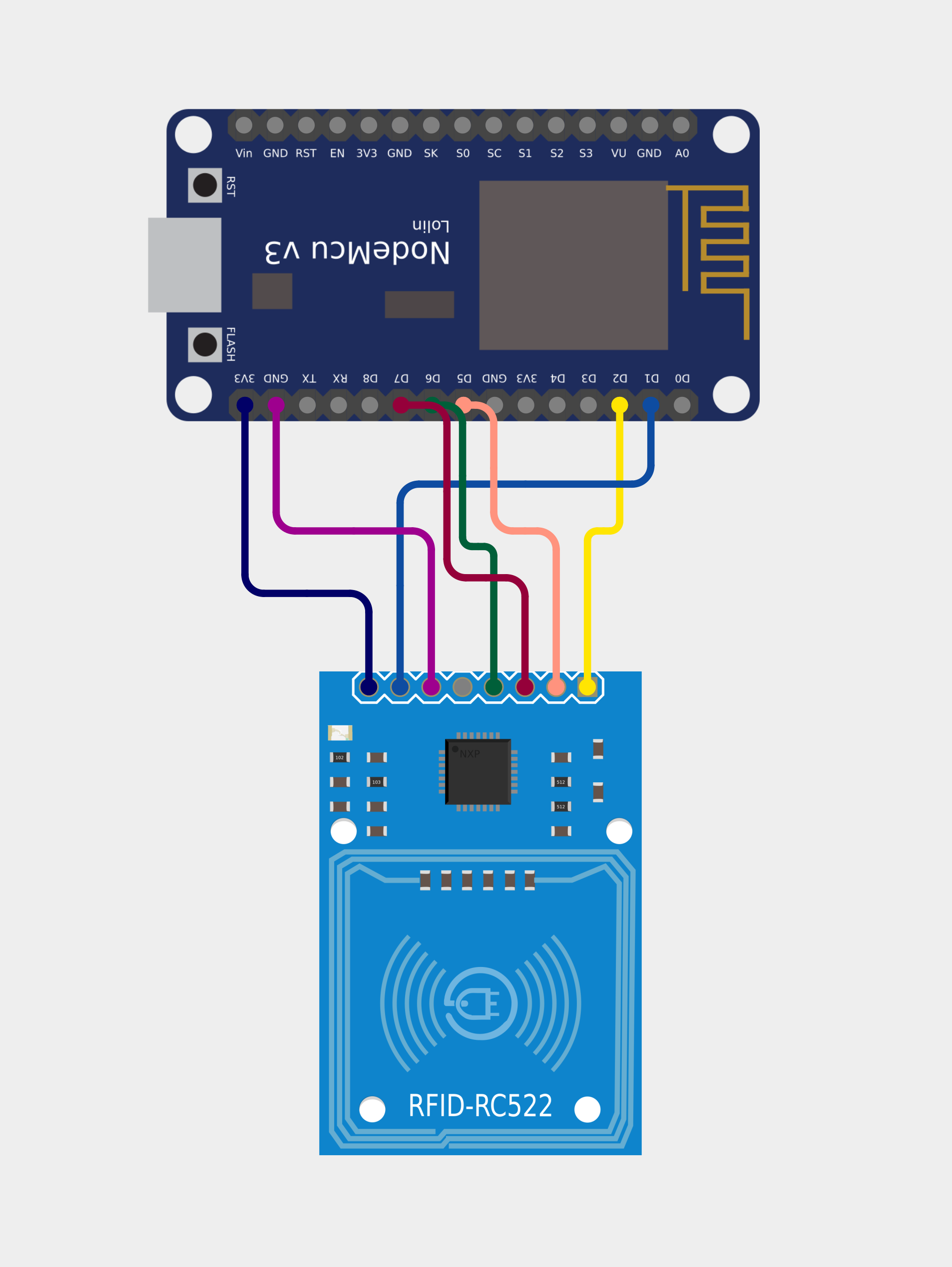
This circuit integrates an RFID-RC522 module with a NodeMCU V3 ESP8266 microcontroller. The RFID-RC522 is used for radio frequency identification (RFID) reading, and the NodeMCU V3 ESP8266 provides Wi-Fi connectivity and processing capabilities. The circuit is designed to read RFID tags and send the tag information to a server via Wi-Fi. The NodeMCU microcontroller is programmed to handle RFID data acquisition, Wi-Fi communication, and HTTP requests.
Component List
RFID-RC522
- Description: An RFID reader/writer module for 13.56 MHz contactless communication.
- Pins: SDA, SCK, MOSI, MISO, IRQ, GND, RST, 3.3V
NodeMCU V3 ESP8266
- Description: A microcontroller board with ESP8266 Wi-Fi module.
- Pins: A0, GND, VU, S3, S2, S1, SC, S0, SK, 3V3, EN, RST, Vin, D0, D1, D2, D3, D4, D5, D6, D7, D8, RX, TX
Wiring Details
RFID-RC522
- 3.3V: Connected to NodeMCU's 3V3 pin for power supply.
- GND: Connected to NodeMCU's GND pin to establish a common ground.
- RST: Connected to NodeMCU's D1 pin for reset control.
- SDA: Connected to NodeMCU's D2 pin for SPI data line
- MISO: Connected to NodeMCU's D6 pin for SPI MISO (Master In Slave Out).
- MOSI: Connected to NodeMCU's D7 pin for SPI MOSI (Master Out Slave In).
- SCK: Connected to NodeMCU's D5 pin for SPI clock signal.
NodeMCU V3 ESP8266
- 3V3: Provides ***** to the RFID-RC522 module.
- GND: ****** ground with the RFID-RC522 module.
- D1: Used for RFID-RC522 reset control.
- D2: *** **** **** for RFID-RC522.
- D6: SPI **** from RFID-RC522.
- D7: SPI MOSI to RFID-RC522.
- D5: SPI clock to RFID-RC522.
Documented Code
Source Code
                    //*******************************libraries********************************

                    //RFID
-----------------------------

                    #include <SPI.h>

                    #include <MFRC522.h>

                    //NodeMCU
--------------------------

                    #include <ESP8266WiFi.h>

                    #include <ESP8266HTTPClient.h>

                    #include <WiFiClient.h>

                    //************************************************************************

                    #define SS_PIN  D2  //D2

                    #define RST_PIN D1  //D1

                    //************************************************************************

                    MFRC522 mfrc522(SS_PIN, RST_PIN); // Create MFRC522 instance.

                    //************************************************************************

                    /* Set these to your desired credentials. */

                    const char *ssid = "TP-Link_55A7";

                    const char *password = "57128979";

                    const char* device_token  = "bbe7e373b85d71a6";

                    //************************************************************************

                    String URL = "http://192.168.0.105:8080/rfidattendance/getdata.php"; //computer IP or the server domain

                    String getData, Link;

                    String OldCardID = "";

                    unsigned long previousMillis = 0;

                    //************************************************************************

                    void setup() {

                    delay(1000);

                    Serial.begin(115200);

                    SPI.begin();  // Init SPI bus

                    mfrc522.PCD_Init(); // Init MFRC522 card

                    //---------------------------------------------

                    //connectToWiFi();

                    }

                    //************************************************************************

                    void loop() {

                    //check if there's a connection to Wi-Fi or not

                    if(!WiFi.isConnected()){

                    connectToWiFi();    //Retry to connect to Wi-Fi

                    }

                    //---------------------------------------------

                    if (millis() - previousMillis >= 15000) {

                    previousMillis = millis();

                    OldCardID="";

                    }

                    delay(50);

                    //---------------------------------------------

                    //look for new card

                    if ( ! mfrc522.PICC_IsNewCardPresent()) {

                    return;//got to start of loop if there is no card present

                    }

                    // Select one of the cards

                    if ( ! mfrc522.PICC_ReadCardSerial()) {

                    return;//if read card serial(0) returns 1, the uid struct contians the ID of the read card.

                    }

                    String CardID ="";

                    for (byte i = 0; i < mfrc522.uid.size; i++) {

                    CardID += mfrc522.uid.uidByte[i];

                    }

                    //---------------------------------------------

                    if( CardID == OldCardID ){

                    return;

                    }

                else{

                    OldCardID = CardID;

                    }

                    //---------------------------------------------

                    //  Serial.println(CardID);

                    SendCardID(CardID);

                    delay(1000);

                    }

                    //************send the Card UID to the website*************

                    void SendCardID( String Card_uid ){

                    Serial.println("Sending the Card ID");

                    if(WiFi.isConnected()){

                    HTTPClient http;    //Declare object of class HTTPClient

                    WiFiClient wifiClient; //Declare object of class WiFiClient

                    //GET Data

                    getData = "?card_uid=" + String(Card_uid) + "&device_token=" + String(device_token); // Add the Card ID to the GET array in order to send it

                    //GET methode

                    Link = URL + getData;

                    http.begin(wifiClient, Link); //initiate HTTP request   //Specify content-type header


                    int httpCode = http.GET();   //Send the request

                    String payload = http.getString();    //Get the response payload


                    //    Serial.println(Link);   //Print HTTP return code

                    Serial.println(httpCode);   //Print HTTP return code

                    Serial.println(Card_uid);     //Print Card ID

                    Serial.println(payload);    //Print request response payload


                    if (httpCode == 200) {

                    if (payload.substring(0, 5) == "login") {

                    String user_name = payload.substring(5);

                    //  Serial.println(user_name);


                    }

                else if (payload.substring(0, 6) == "logout") {

                    String user_name = payload.substring(6);

                    //  Serial.println(user_name);


                    }

                else if (payload == "succesful") {


                    }

                else if  (payload == "available") {


                    }

                    delay(100);

                    http.end();  //Close connection

                    }

                    }

                    }

                    //********************connect to the WiFi******************

                    void connectToWiFi(){

                    WiFi.mode(WIFI_OFF);        //Prevents reconnection issue (taking too long to connect)

                    delay(1000);

                    WiFi.mode(WIFI_STA);

                    Serial.print("Connecting to ");

                    Serial.println(ssid);

                    WiFi.begin(ssid, password);


                while (WiFi.status() != WL_CONNECTED) {

                    delay(500);

                    Serial.print(".");

                    }

                    Serial.println("");

                    Serial.println("Connected");


                    Serial.print("IP address: ");

                    Serial.println(WiFi.localIP());  //IP address assigned to your ESP


                    delay(1000);

                    }

                    //=======================================================================
This code is designed to run on the NodeMCU V3 ESP8266 microcontroller. It initializes the RFID-RC522 module and sets up Wi-Fi connectivity. The main loop checks for new RFID cards, reads their UID, and sends the UID to a specified server using an HTTP GET request. The code also includes functions to handle Wi-Fi connection and reconnection.
Making Process
Please watch the full video above to understand the making process.
Circuit Diagram